Ashton Roskill’s Eleven Rebuild
By Alister Rees.
As a follow-on from the article in the April edition regarding the Automotive Craftsmen Shed Tour and Ashton Roskill’s Eleven, we plan to give monthly progress reports detailing the repair journey of this classic piece of Lotus history.
Part 1
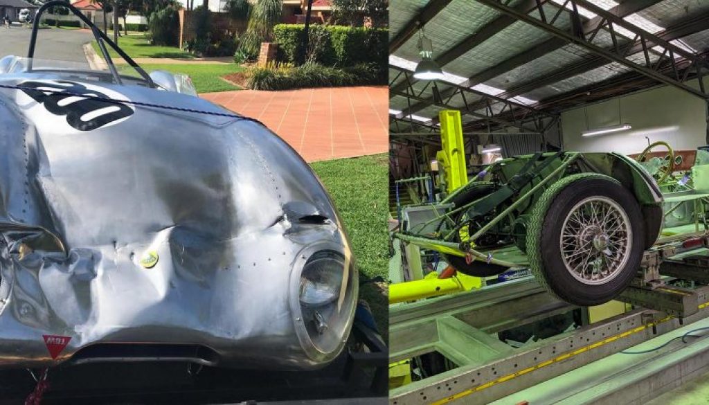
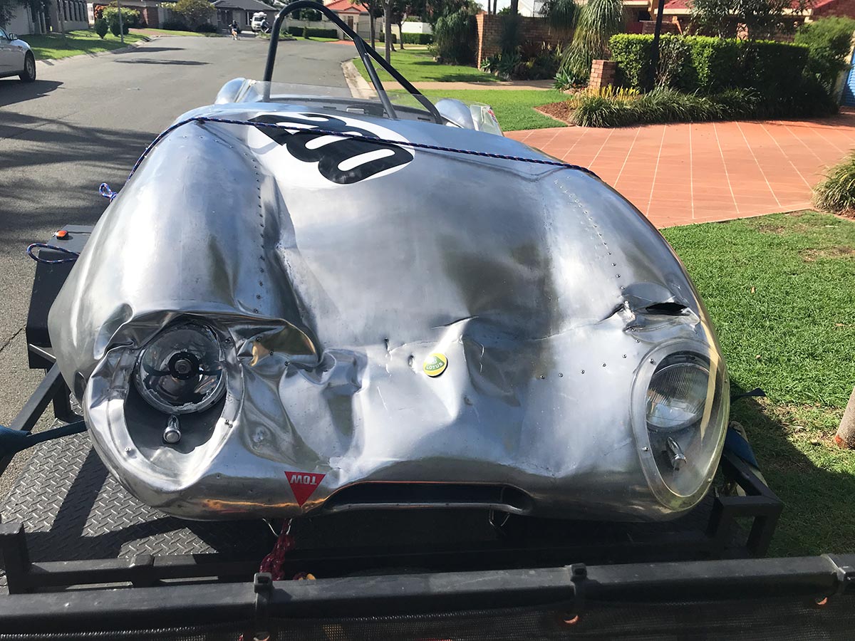
The story started when we were contacted by Ashton in March 2019 and he sent some initial photos of the damaged car. We requested further photos from different angles and after studying a myriad of different shots, we were able to arrive at an initial estimate based on the information gleaned from these photos. From our understanding the damage was mostly isolated to the front end. The fabrication of a new front clam was the focus of this repair.
We then began a drawn-out procedure communicating with an assessor in Sydney who unfortunately appeared to have little knowledge of Lotus of any type, especially not a thoroughbred from the fifties.
After several months of challenging discussions and delays the Eleven finally arrived at our workshop in late October 2019. With the move to Queensland a new assessor was then appointed by Shannons, and we were able to move forward with a proper physical assessment of the damage.
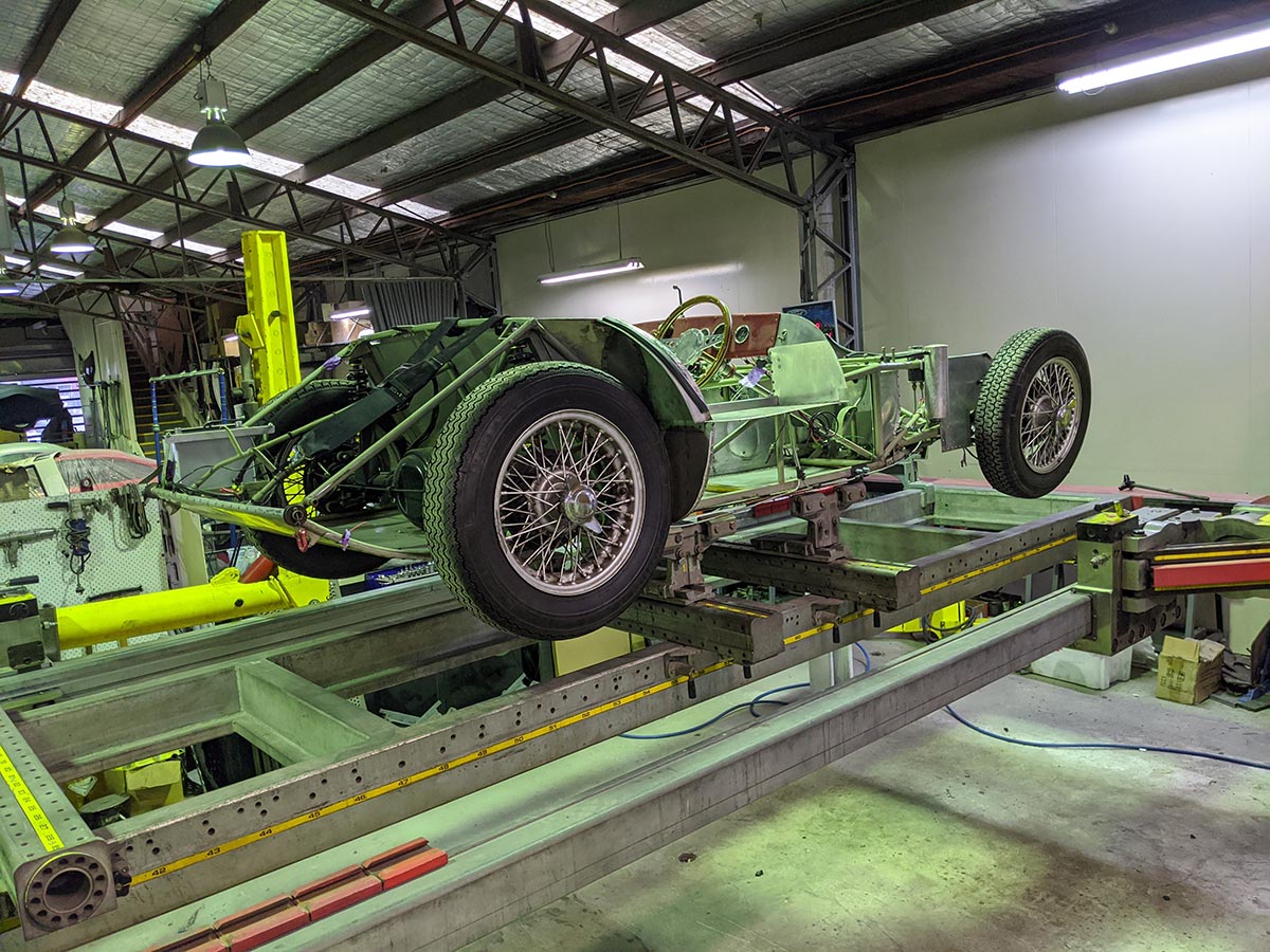
Once we were able to get the vehicle in the air for a full inspection it became apparent there was other damage not able to be photographed while on the ground.
The final assessment included: Twisted chassis (front and rear), under-body skin damage, front and rear shocker damage, damaged wheel bearings, bent swing arm, buckled wheels and intake manifold gasket damage. All this adding significantly to the original estimate.
Ashton was able to recommend a parts supplier in the UK and we duly contacted Mike Brotherwood with a parts list. We would like to acknowledge the assistance of Tony Galletly who has been a great help in many areas and has a wealth of knowledge after his Eleven restoration.
Once we received the parts quote from Mike, we were able to submit our firm quotation to Shannons. Final approval was duly received on 28 November 2019. We commenced work on 2 December, placed the parts order and started stripping the car.
First task was to dismantle all the damaged components. After drilling out 680 rivets to remove the floor trays and sill panels, the bare bones of this iconic design were exposed. The simplicity of this car is an amazing sight. After the outer body had been removed, next up was the mechanical.
Documenting each part and its orientation, gave us the understanding we need to see the car through the eyes of its creators. Knowing how the designer intended the car to be, ensures Ashton’s Eleven will be repaired correctly and retain its originality. With the vehicle stripped down to the bare minimum for transport, it was time to re-align the chassis.
We would like to acknowledge the assistance of Nick Contarino at Exclusive Auto Centre for the use of his state-of-the-art Car Bench chassis alignment system, to restore the Eleven’s frame to the original dimensions and alignment.
Before founding Automotive Craftsmen, Adam served his apprenticeship at Exclusive Auto Centre, and was awarded Apprentice of the year for Queensland in 2014. He was also runner-up in the National World Skills Competition held in Perth the same year. Luke also spent approximately two years at Exclusive Auto Centre repairing Ferrari and Lotus, (including composite repairs), after completing a panel beating and spray-painting apprenticeship in Sydney.
Part 2
This month considerable progress has been made on the manufacture of the new front clam for Ashton Roskill’s Series One Eleven.
The reason a new front clam is being manufactured, is that it was not economically viable to repair the original to an acceptable level.
Part of the Automotive Craftsmen philosophy is “nothing is impossible to repair” however, economic reality must prevail, and sometimes it is more viable to build a new part.
Working with aluminium presents some unique challenges compared to steel, particularly 50-year-old aluminium that has been repaired before.
It is safe to say that with these classic hand-built cars from the sixties, most have had a few hits in their life, and if the previous repairs have been carried out by someone without an intimate knowledge of the intricacies of the material, this can present some challenges when the vehicle is involved in another shunt in the same area.
This was the case with Ashton’s car, as earlier in its life it had a new section replaced from the leading edge to just behind the headlights. (The weld line can be seen just above the badge in Photo No.1).

The quality of the weld leaves a little to be desired, and when these welds were dressed, quite a bit of material was removed in the surrounding area and the skin is very thin. After a detailed inspection there were several other areas where weld lines were beginning to fracture.
Another problem with this new front section that had been fitted, was the wing shapes were not symmetrical and the headlight pods were not correctly aligned. All these issues made the decision to make a new clam the only real option. All that remained was to sell this concept to the insurance assessor, which I am pleased to say we accomplished.
Traditionally, coachbuilding has been done over a timber buck or wire frame, however it is not always viable to make a timber buck for a one-off repair, and the coachbuilder has other options to choose from.
In this case Adam elected to repair the damaged clam, and use this as the buck, which gives the added advantage that Ashton has the option to use the repaired clam for track events.
The most severe damage was to the RH front corner. To re-instate this, required many hours of working and unfolding the aluminium to carefully massage it back to shape. The LH side also sustained damage around the headlight area, and while not as serious, still required considerable time and skill to hand form the 50-year-old aluminium. The damaged areas were now restored to the point where the aluminium was back to a neutral state.(Photo No.2)

To ensure the correct profile and shape were achieved, considerable research had been carried out using photographs from magazines and the internet to find the correct shape so this classic could be returned to the original design.
An obvious essential skill of a good coachbuilder is an excellent eye for line and detail, (far better than we mere mortals) and this is critical when working with compound curves and converging lines.
Once the original clam was repaired (75 hours) a decision was made to use the LH side to make the patterns and profiles, as it was considered identical to the original shape. Using traditional templating methods mixed with some modern materials, we were then able to copy the exact surface dimensions, panel lengths and join locations. This method is called the flexible shape pattern. As an added feature, the same templates and patterns can then be reversed and used on the opposite side. This gives the ability to create a symmetrical part. (Photo No. 3 & 4)


From these patterns, 18 pieces of 5005 aluminium were then cut to size. (Photo No. 7)

Using the traditional wooden stump, blocking hammers and the English wheel, many hours were then spent forming each piece. Gauging the shape by hand and eye, then fitting each individual section to the templates.
With all 18 parts fabricated and defined, the next task is matching the sections with each other. Taking 2 sections at a time, blending the shape into one another and fusion welding them into a single part. This weld line is then worked on the wheel to form a continuous even profile and trial fitted to the buck to check the form. A total of six pieces were then welded to form the new left front wing. (Photo No. 11)

Now sharp, precise and symmetrical, the iconic Series 1 Lotus Eleven shape was recognisable. The same process was then repeated for the right wing.
The next stage was to refine the shape of the centre bonnet skin. At first glance this would appear to be a relatively simple shape but was in fact the most difficult section to manufacture. Having such a subtle amount of shape at the rear then transitioning gradually to a full shape towards the nose of the car, provided a real challenge to achieve a consistent and even surface. For five full days, yes that’s FIVE, Adam and Luke shaped this bonnet together on the wheel in complete synchronization. With all the skills, attention to detail and patience, it still required 3 skins to be shaped to get the finished product that you see here. (Photo No. 5 & 6)


Perfection is never achieved without effort, and with such a highly polished finish the smallest ripple would be visible.
Now was the time to join the left and right wings to the centre bonnet skin. This is the stage that will make or break the front clam fabrication. Using the 3D templates and marking out the exact trimming point, Adam slowly made the surgically accurate cuts that will be the final join of this month-long endeavour for perfection. With a final check of all profiles and dimensions, the tack welding and fusion process starts. If any stage of the process is skipped or miscalculated, this will have serious consequences on the finished product. After the three major parts are fused into one, it is very gratifying to see the end result with all major reference points aligning. (Photo No. 12)

Total labour to fabricate new front clam to this stage — 312 hours
Part 3 – New Front Clam
Progress has been slower than anticipated, due to restrictions around the Covid 19 challenge that has affected most businesses in Australia.
In the June edition we finished at the stage where the three main sections of the new front clam were tack welded and fused into one piece with all major reference points aligning.


As this front clam is going to be file finished and polished, the two main welds that join the front wings to the bonnet are critical in their execution. Each of these weld runs is 1.4 metres long and must be performed in one continuous operation (photos 1 & 2). Any variation in pace will cause a blow hole if too slow, or a shallow weld if the pace increases slightly. Shallow welds are a serious problem, as over time these will crack from the continual vibration.
NOTE — to put this in context, this is two pieces of 1.6mm thick aluminium, edge to edge !
When these welds are completed, the clam is flipped over and the same process is repeated on the inside.
To add to the challenge, the new body has been shaped freehand over one side of the original body, (as mentioned in the June edition) as we are working without a buck. This can cause slight variations in the joins that need to be corrected in the file finishing stage, adding more tedious checks and test fitting over the chassis to ensure both the shape of the new front clam and the alignment with the car are correct (photo 3).


As the part is now too large to fit through the English wheel, these welds must now be dressed and blended out by hand using a variety of hammers and dollies, to bring the welded area to the same thickness as the surrounding metal. (At last count Adam has 43 hammers and 57 different shape dollies.)
With these final welds now blended in, the next step before file finishing can begin, is to fabricate a temporary brace to be tack welded across the rear edge to give some rigidity to the panel during the file finish process (photo 4). Once this is completed this brace will be removed (too heavy) and a 4mm stainless wire edge will be rolled in (to add lightness).
It is now time to start the file finish process which will initially be done on the centre section out to the centreline of the front wings. This area needs to be completed before the grille opening section can be fitted.
At this point I would like to give the reader an explanation of the file finishing procedure and why it is necessary.
The file finish process was used extensively in the “old days” to achieve a quality finish along with lead wiping on steel panels that were then painted. However, with the advent of polyester fillers in the 1960s, and under increasing pressure from insurance companies to drive down costs, file finishing became a dying art, now practiced by only a limited number of skilled craftsmen, when specified by discerning clients.
Now back to aluminium — An off-the-wheel finish is satisfactory if the body is to be painted, as any minor blemishes left by the wheel are faired with polyester filler before priming. However, as this car must retain its exposed aluminium finish, fillers of any kind cannot be used, so the file finishing is necessary to achieve the polished surface.
File finishing is essentially the process of refining the shape. This means adjusting the profile by hand, using specialist hammers and dollies to flatten any minute highs, stretching low points around join lines and correcting the overall curvature of the panel.
First a guide coat is sprayed on the surface (fast drying etch primer), then using a body file with light pressure across the surface, the guide coat is removed from the high areas and is left on the low areas, giving the “guide” to where the metal must be raised or lowered. (photo 5).
The highs are carefully massaged using a body-spoon. Then the low areas are stretched using a slapping file while holding the correct shape forged dolly tool under the skin.
A final check spray of guide coat is then applied, and the process repeated until a smooth flowing body shape is ready to be sanded. (photo 6)


The file is only used to highlight any highs or lows in the surface, NOT to remove metal, so that all minute blemishes in the surface are painstakingly removed by massaging the metal to a perfect form, rather than grinding and thinning out the material.
This is what defines a coachbuilding artisan from a panel beater (with all due respects to panel beaters of course) and will give the reader a clear understanding of why a polished aluminium body is a rare sight these days.
The skill sets required to achieve a true file finish for polished aluminium, requires a level of natural ability and skill that is very rare. The hand eye coordination, and the ability to “feel” the metal surface with the hand, is the reason the perfect file finish is so difficult to achieve.
Once this process was completed on the centre section, the next task was to fabricate the tubular grille frame and mounting points that hold the entire front clam onto the car. With the new frame fabricated, the grille opening skin was formed over the frame, creating the beautiful rounded edge of the Eleven’s distinctive front.
We then welded the grille opening skin into the front clam, (photo 7). The sub-assembly (consisting the tubular grille frame welded to the mounting points) was then fitted to the clam skin, and the front clam was trial fitted to the chassis for the first time. (photo 8)


Part 4 – The New Clam continued
In last month’s report we had arrived at the stage of the successful first trial fit of the bare skin to the chassis. The next stage is to fabricate the headlight buckets, then align and weld them into the correct position.
At first glance the buckets look simple enough – roll up a couple of cylinders, weld on a backing plate, no worries – job done.

Life is not always that simple in Lotus land, so to make things exciting the bucket is tapered. Fortunately, we were able to make a flexible pattern from one side of the original clam, to give the required shape to cut the aluminium before rolling the tapered tubes.
The mounting rings were then fabricated with a 6mm edge turned out at 90 degrees to stiffen the mounting ring for the headlight assembly. (Photo 1). (Looks easy but is a time-consuming process). Most fabricators would simply use a piece of 3mm aluminium for this mounting ring, but that definitely would NOT be adding lightness.


These rings are then welded to the conical tubes (Photo 2) The bucket and recessed area on the clam are then scribed and trimmed VERY carefully to give an accurate join line ready to tack weld into place (Photo 3). The perimeter is then fully welded. (Photo 4).


The final stage is to dress and file finish this perimeter weld (Photo 5). A few moments studying this photo gives an indication of the patience and skill levels required to achieve this result on such a complexity of converging angles and compound curves.


Once the headlight buckets were completed the next major task was to fit the 5mm stainless wire edge around the perimeter of the clam. The major challenge with this task is to ensure the shape that has been so laboriously created, does not move when the wire edge is rolled in. This process cannot be done with the clam sitting on the chassis to maintain alignment but must be done upside down on the bench.
To ensure the true lines are maintained, a series of profile gauges were made so the shape can be continually checked during the process (Photo 6)
Once the clam is trimmed to its final shape around the front edge and wheel arches (including a 13mm allowance for rolling around the wire), the challenge is to then dress this 13mm edge at 90 degrees to the body, and maintain the consistency as it flows around the compound curves of the front and into the wheel arches. (Photo 7).

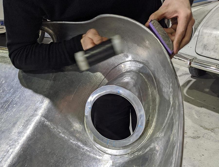
The pre-bent wire is then placed into the corner and clamped in place with vice grips (Photo 8), while the edge is rolled over with a nylon-faced hammer and a sheathed steel dolly. (Photo 9).

The final dressing of the rolled wire edge is done with a modified vice-grip and sacrificial strips of aluminum to avoid gouging the edge.
When the wire edge is completed across the front and around both wheel arches, the clam is now fitted back to the chassis to mark the final trim line for the rear edge of the clam. Once this rear edge is trimmed and the wire rolled in, the temporary braces (Photo 10) are removed and the wire edge process is complete.
Part 5 – Chassis Restoration May 2021
The story continues from when we had progressed to the point where Ashton’s Eleven was now completely stripped down to the bare chassis.
After a thorough clean down and visual inspection, there were several issues that needed to be addressed
before the chassis was sent for sandblasting.
The first one to be rectified, had been identified earlier while dismantling the front suspension. We noticed some serious rub marks on one of the front chassis tubes where the coil spring shocker unit had been binding on the tube. When the new Spax Shocker Units and lower mounting brackets arrived from Mike Brotherwood, we trial fitted them to the chassis to adjust the clearance between the spring/shocker unit and the chassis. One of the new shocker brackets was machined 0.75mm oversize and would not fit through the rod end on the control arm (photo 1). This is an” L” shaped bracket, which was a challenge to set up in the lathe, but after several creative hours we achieved the correct tolerance.
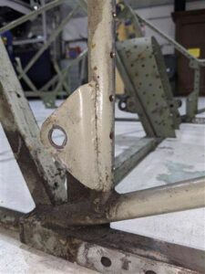
Another problem we noticed when removing the original aluminium floor skin, was that the section of the chassis from the rear bulkhead back, had a 20mm kink (when viewed from above), in the lower chassis tubes (photo 2). The aluminium floor skin for this area had been trimmed to suit this misalignment (photo 3). As this appeared to be the original floor skin, this misalignment had obviously been there all along. We were able to realign this rear section that supports the rear bodywork, by setting the chassis up on the alignment bench and applying a load, to bring this section back into correct alignment.
There are two jacking points on the front of the chassis, and one of these had been highly loaded at some point in its life. The jacking point had deformed and crushed the chassis tube. The tube was repaired, and the jacking point straightened and re-welded.
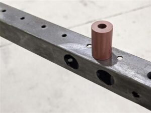
We found some potentially serious safety issues on the chassis, where the roll bar mounting bolts had been overtightened and the bolts had started to pull through the tube. The tubes in this area of the chassis are of square section, so the tube was repaired, and crush tubes machined, (photo 4) and welded in position to provide a safer mounting system for the roll bar. The same tube damage had occurred at the exhaust mounting points, so these tubes were also repaired, and crush tubes inserted.
There are over 120 welds throughout the chassis, but there were only seven that showed stress cracking. These were meticulously cleaned and re-welded. One of these was a rear control arm mounting bracket which had a severe stress fracture (photo 5) and was at risk of detaching itself from the chassis.
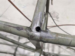
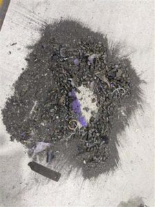
The next challenge was to remove all the rivet tails that were now in the chassis tubes from when the rivets were removed from the aluminium skin. To facilitate this, holes were drilled in the tubes at strategic points to allow their removal. (photo 6). Once all debris was removed (to add lightness), (photo 7) these holes were then re-welded.
With all rectification work completed, the chassis was now ready to be sandblasted. Unfortunately, we had a delay in this process as there is only one company in the Brisbane area we trust to perform the task on a lightweight chassis, and of course they are always busy.
We had it booked to be done before Christmas but due to unforeseen circumstances, they were unable to do it before their 4-week shutdown. However, Peerless Sandblasting did an excellent job and we received the chassis back in mid-February, so it was well worth the wait.
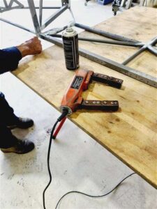
The next step in the process was to have the chassis crack tested. This was carried out by IRIS NDT who came to our workshop and performed magnetic particle testing (photo 8).(This identified a further five cracks that were not visible to the naked eye. These additional cracks were then re-welded, and the chassis was now ready for painting.
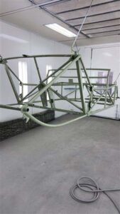
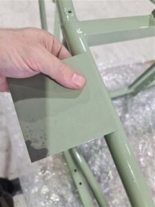
This was carried out by our preferred Spray Painter, Old School Garage, who applied a premium grade epoxy primer, followed by Glasurit 2 pack high gloss, colour matched to the original acrylic used by the factory. (photos 9 & 10).
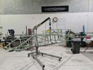
The final step in the chassis restoration was the weigh-in! Carefully suspended from our engine crane the digital scales showed 24.3kg. Now there’s a great example of lightweight engineering from Colin Chapman (photo 11).
It appears this is another material that is in short supply due to plant closures caused by the Pandemic, as there has been no stock in the country since late 2020. There is plenty of 0.4mm available which is the most popular for aircraft work.
We anticipate this will arrive in Australia in late May, and we can then resume work on the project, and get this iconic piece of Lotus history back on the road again and put a smile on Ashton’s face.
